Home : Gallery : History : Uses : Behaviour : Maths : Forum : Propulsion : Links : Glossary
Behaviour
In depth
 
To download an Acrobat version (41K): click here

How a gyroscope works

By Cef (Terry) Pearson
Cef's Website: click here

I have searched through many texts. But I have never found an explanation of why a gyroscope should resist being turned in any direction perpendicular to it's axis. Maybe the workings of a gyroscope seem obvious to some and needs no explanation. But still, other obvious physical phenomena are explained. So here is the first published (that I know of) account of the physics behind how a gyroscope works.
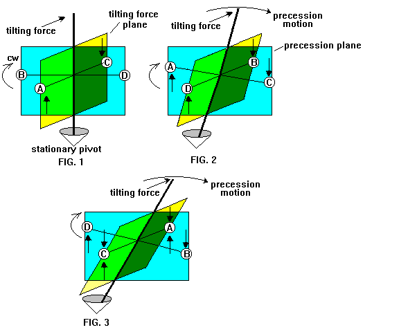
Here is a pictorial of a simplified version of a gyro.
Instead of a complete rim, four point masses, A, B, C, D, represent the areas of the rim that are most important in visualizing how a gyro works. The bottom axis is held stationary but can pivot in all directions.
When a tilting force is applied to the top axis, point A is sent in an upward direction and C goes in a downward direction. FIG 1. Since this gyro is rotating in a clockwise direction, point A will be where point B was when the gyro has rotated 90 degrees. The same goes for point C and D. Point A is still traveling in the upward direction when it is at the 90 degrees position in FIG 2, and point C will be traveling in the downward direction. The combined motion of A and C cause the axis to rotate in the "precession plane" to the right FIG 2. This is called precession. A gyro's axis will move at a right angle to a rotating motion. In this case to the right. If the gyro were rotating counterclockwise, the axis would move in the precession plane to the left. If in the clockwise example the tilting force was a pull instead of a push, the precession would be to the left.
When the gyro has rotated another 90 degrees FIG 3, point C is where point A was when the tilting force was first applied. The downward motion of point C is now countered by the tilting force and the axis does not rotate in the "tilting force" plane. The more the tilting force pushes the axis, the more the rim on the other side pushes the axis back when the rim revolves around 180 degrees.
Actually, the axis will rotate in the tilting force plane in this example. The axis will rotate because some of the energy in the upward and downward motion of A and C is used up in causing the axis to rotate in the precession plane. Then when points A and C finally make it around to the opposite sides, the tilting force ( being constant) is more than the upward and downward counter acting forces.
The property of precession of a gyroscope is used to keep monorail trains straight up and down as it turns corners. A hydraulic cylinder pushes or pulls, as needed, on one axis of a heavy gyro.
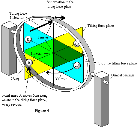
Sometimes precession is unwanted so two counter rotating gyros on the same axis are used. Also a gimbal can be used. THE GIMBALED GYROSCOPE Fig 4 The property of Precession represents a natural movement for rotating bodies, where the rotating body doesn’t have a confined axis in any plane. A more interesting example of gyroscopic effect is when the axis is confined in one plane by a gimbal. Gyroscopes, when gimbaled, only resist a tilting change in their axis. The axis does move a certain amount with a given force.

A quick explanation of how a gimbaled gyro functions

Figure 4 shows a simplified gyro that is gimbaled in a plane perpendicular to the tilting force. As the rim rotates through the gimbaled plane all the energy transferred to the rim by the tilting force is mechanically stopped. The rim then rotates back into the tilting force plane where it will be accelerated once more. Each time the rim is accelerated the axis moves in an arc in the tilting force plane. There is no change in the RPM of the rim around the axis. The gyro is a device that causes a smooth transition of momentum from one plane to another plane, where the two planes intersect along the axis.

A more detailed explanation of how a gimbaled gyro functions

Here I attempt to show how much the axis will rotate around a gimbaled axis. That is to say, how fast it rotates in the direction of a tilting force.

In figure 4, the precession plane in the gimbaled example functions differently than in the above example of figures 1-3, and I have renamed it "stop the tilting force plane". The point masses at the rim are the only mass of the gyro system that is considered. The mass and gyroscope effect of the axis is ignored.

At first consider only ½ of the rim, the left half. The point masses inside the "stop the tilting force plane" share half their mass on either side of the plane, and add their combined, 1/4kg, mass to point mass A of 1/2kg. So then the total mass on the left side is ½ the total mass of all 4 point masses, or 1kg. The tilting force will change the position of point mass B and D very little and change the position of point mass A the most. So we must use the average distance from the axis of all the mass on the left-hand side.
Fig 5
The mass on the left side is 1kg. The average distance the mass is from the "stop the tilting force" plane is 1/2 meter. Figure 5 shows a profile of the average mass in the tilting plane and the average distance from the axis that the mass is situated. We are concerned at how far the mass at the average distance will rotate within the tilting plane when a given force is applied to the axis in the direction indicated.

Point mass A is rotating at 5 revolutions per second. This means that it is exposed to the tilting force for only .1 seconds. The tilting force of 1 Newton, if applied for .1 second, will cause the mass at the average distance to move .005 meter in an arc, in the tilting force plane. Since the length of the axis is twice as long as the average distance of the rim’s mass, the axis will move .01 meter in an arc. At the end of .1 second the point mass will be in the "stop the tilting force plane" and all the energy transferred to point mass A is lost in the physical restraint of the gimbal bearings.

The same thing happens when point mass A is on the right side of figure 4. Only now, the tilting force will move point mass A down, and the axis will advance another .01meter. .01 meter every .1 second is not the whole story because the mass on the right side of the gyro hasn’t been considered. The right side has the same mass as the left and has the same effect on the axis as the left side does. So the axis will advance half as much, half of .01 meter, or .005meters. Both halves of the rim mass will pass through the stop the tilting force plane 10 times in one second. Each time a half of the rim passes though the "stop the tilting force plane", it losses all its momentum that was added by the tilting force. The mass has to undergo acceleration again so we continually calculate the effect that 1 Newton has for .1 second on the rim mass at the average distance, 10 times a second. So then; at the point that the 1 Newton force is applied, the axis will move 5cm per second along an arc. The gyro will rotate at .48 RPM within the tilting force plane.

What considerations does the rim speed have on the distance that the axis will rotate along an arc in the tilting force plane?

The gyro will rotate in the tilting force plane, half as fast if the rim speed is doubled.

What happens when the mass of the rim is doubled?

The gyro will rotate in the tilting force plane, half as fast if the rim mass is doubled

How does the rim diameter effect rotation in the tilting force plane?

The gyro will rotate in the tilting force plane, half as fast if the rim diameter is doubled

The Math of a gimbaled gyro

1 Newton = 1kilogram 1 meter sec.2

F=ma

d=1/2 X (a X t2 )

1 Newton acting on 1kg will accelerate the mass at a rate of 1 meter sec^2

the time that ½ the mass of the rim is exposed to the tilting force at 5 revolutions a second is 10 times a second or 1/10; .1 sec

The distance, d, the mass will go in .1 sec
d = ½ X 1m / sec2 X (.1sec)2 ; = ½ X 1m/sec2 X .01 sec2 = .005 meter

The axis is twice as long as the distance from the average distance that the rim mass is calculated from .005 X 2 = .01 meters

Now consider the other side of the gyro as acted on by the same 1 Newton force.
.01m / 2 = .005

The force will have ten times a second to accelerate the rim mass from a relative velocity of 0m /sec.
 10 X .005m = .05m; or 5 centimeters
 

Years ago there was a news story about a man that used a gyro to produce more energy than was needed to keep the gyro spinning. He used a surplus ship's directional gyro. I think what he did was use the property of precession to run a generator.
If left undisturbed, a gyro on the surface of the Earth would turn 360 degrees once every 24 hours. The top of the gyro would normally go westward. But if the top axis were held so that it could not rotate from east to west, due to precession, the gyro will rotate in the north and south direction depending on the direction the rim is rotating. The gyro would turn due to precession until it reaches 90 degrees with it's axis pointing north and south. Then it would be in the same plane as the rotation of the Earth and gyroscopic precession would stop. To get the gyro out of the Earth's rotational plain a small force could be applied to the gyro axis and precession would put the axis back in the original position. The 90 degree precession rotation would be much faster than the once per 24 hours opposing forces rotation, but some gearing would probably still be needed to run a generator. The generator would be mechanically linked to the precession back and forth motion in one direction only so it will turn the same direction all the time. The amount of energy needed to keep the gyro's rim spinning and the energy needed to turn the gimbals back 90 degrees would determine the overall efficiency.
This is NOT a free energy thing. The energy comes from the rotation of the Earth and therefore the Earth rotational speed is slowed as energy is tapped from a gyro-generator type machine. If this method of generating energy is used to a great extent, days and nights would become longer. If this should happen. let me be the first credited to use the term "rotation pollution" or "motion pollution".

Other experiments with a gyro
There might be a way to accelerate the rotational speed of the rim of a gyro by using a short duration tilting force on the axis. The force's duration would be for much less then the length of time that is required for the rim to rotate 90 degrees. When the rim has rotated 90 degrees from the time the tilting force was first applied, The tilting force would be purposely reversed. The direction that the rim is rotating and the direction the rim would have moved due to precession are now close to the same. The two motions might combine and result in an increase in the rotational speed of the rim. T

To download an Acrobat version (41K): click here
Website. Copyright © 2025 Glenn Turner. All rights reserved. site info
Do not copy without prior permission. Click here for gyroscope products