
|
|
|
|
|
|
||||||||||||||||||||||||||||||||||||||||||||||||||||||||||||||||||||||||||||||||||||||||||||||||
Gyroscopic Propulsion
What do these "Propulsion devices" do?The concept is to produce a gyroscope based device that can produce sufficient amounts of lift/force to be detectable and useful. In an extreme case this may mean that the machine could lift its own weight and hence is able to fly or just to push something along. However research is still in its early stages and I've yet to see one that can create any force under proper test conditions.
The use of the term "Anti-Gravity Device"The use of the term "Anti-Gravity Device" is sometimes associated with this type of device. This is misleading and confusing in many ways and I don't believe the term should be used. It is highly unlikely that these type of devices effect gravity in any way. I believe the forces are independent of gravity and more related to the gyroscopic forces. From the evidence Iíve seen, if these devices really do produce force I believe energy is some how converting from rotational energy to a linear thrust. Then these 'machines' can be put to better use in space with a zero or micro gravity environment.
Are these devices related to zero point energy?As far as I'm aware none. In fact great amounts of energy has to be put in to get any linear force out (if any). Uses for gyroscopic propulsion devicesGyroscopic propulsion would have a number of uses on land, sea, air and space. What uses the device can do depends on the amount of force produced and its efficiency to produce that force. It may turn out that they can only ever produce a force a fractional of the weight of the device e.g. a 10Kg device give 1% thurst = 100g thurst. The weight to thrust ratio will define whether the technology can be used on land, sea and in the air. However in space the devices come into there own and they would be useful even if they could only produce a small thurst compared to theier mass. Rockets are used almost exclusively as a means of propelling something in space and although inefficient, it is the best we have at present. Assuming gyroscopic propulsion does work it provides a means of getting from A to B in space without taking your fuel up too. The devices could simply be solar powered so the fuel won't run out. Of course the device still needs a way to get it into space in the first place.
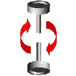
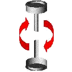
Sandy Kidd and Force Precessed GyroscopesA simplified description of force precessed gyroscopesIn the following set of diagrams red arrows are used to show the force applied to the structure. Provided the gyroscopes themselves are rotating in the correct direction (not shown on diagram) the gyroscopes will produce a counter-acting force known as precession, as shown in the diagram as two blue arrows. Normally this would produce a continuous torque as the whole device is revolving which would cancel it self out in the form of stress in the structure of the machine. However in Sandy's patent the gyroscopes are pushed in/out using cams resulting in the following motion (represented by the eight diagrams). As far as I can understand a number of up-ward pulses are produced due to the two gyroscopes (in this particular case, more can be used) exerting a force towards the centre of the structure (axle). This in effect is a vastly simplified version of what is going on. A number of independent tests have shown results for and against the machine.
SIDE VIEW


TOP VIEW


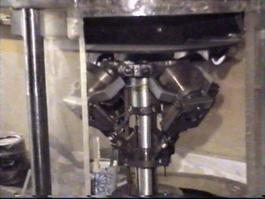
While working in the Air Force, Dundee based engineer Sandy Kidd was one day taking a gyroscope out of an aircraft. Not realising that the gyroscope was still running, he came down the steps of the aircraft and turned at the base of the steps. At this point the gyroscope almost threw him across the floor. This stirred his interest in gyroscopes, Sandy spent many years and tens of thousands of pounds in his garden-shed/garage developing and working on gyroscopic devices. Trying to get a number of gyroscopes to react against one another to produce lift. In time he developed a device that he claimed could achieve this. Building other models using that principle and discussing his ideas with others, he came to conclusions of how it worked. Dundee University was interested in the invention and for a time worked with him, but long term could not supply the funds or enthusiasm that was needed. He tried obtaining funds to develop his invention in Scotland, but had to resort to looking for funds elsewhere. An Australia corporation BWM took the task on to develop a gyroscopic propulsion system but unfortunately the company went bust. British Aerospace has also been involved in the research with him but dropped the funding. A UK/European patent for his invention was applied for (I have a copy of the application). I did try to find a granted patent for Europe but without success. I ended up phoning the European patent office to find out if one was granted. I was told that it would have been, but it was withdrawn at the last moment (funding dropped). I did however find a granted US patent (5024112). The fees for the patent have stopped being paid for some years ago. Which means anyone is free to copy, sell etc his invention (At least in the US/Europe).
Sandy is still working on various devices based around gyroscopes and hopefully
we will be seeing more inventive designs from him in the near future. Image: Copyright Grampian Television PLC Dr Bill Ferrier of Dundee University talking about Sandy Kidd's machine in 1986: "..............There is no doubt that the machine does produce vertical lift. Several modifications were then made at my suggestions in order to disprove other possibilities of lift, particularly aerodynamic effects. I am fully satisfied that this device needs further research and development. I have expressed myself willing to help Mr Kidd whose engineering ability is beyond question, and for whom I now have the greatest respect. I am currently trying to interest the university in housing the development and also in finding 'enterprise' money to fund the next stage. I do not as yet understand why this device works. But it does work! The importance of this is probably obvious to the reader but, if it is not, let me just say that the technological possibilities of such a device are enormous. Its commercial exploitation must be worth millions." Professor Eric Laithwaite
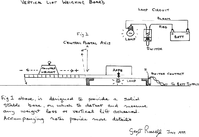
(14th June 1921 - 27th November 1997) Image: Copyright Grampian Television PLC Geoff Russell (Geoffrey C Russell)July 1999 I got in contact with Geoff Russell (Patent No.2,090,404). He tells me that the machine based upon his patent has changed quite a lot. Vast improvements have been made over the years and he now has a device that he says "weighing 22lb, which was able to consistently register weight loss or vertical lift pulses of 20lb, give or take the odd oz". He has very kindly given me diagrams and notes on one of the ways that he tests his devices 
"Notes on Fig 1 Vertical Lift Weighing Board Fig 1 is designed to detect and measure any vertical lift being generated by your machine. This is achieved essentially by providing a stable base on which to test your apparatus. While leaving the base and apps free to tilt vertically upward, in response to any vertical lift being generated. Fig 1 consists of a flat rigid wooden board approx. 1" Thick, the overall size of which should be determined by the size and weight of your own apparatus. The board has two L shape aluminium sections attached to its underside. With the first positioned at the central pivotal axis and the second positioned at one end of the board. A contact switch is attached to this aluminium section so that it operates, lighting an indicator lamp each time the board tilts upward loosing contact with the ground. A counter weight approx. the same weight as your apparatus is also required to vary the balance of the board. By varying the position of the board movement of the counter weight towards the central pivotal axis of the board, would mean that your apparatus would have to generate greater vertical lift to light the indicator lamp. Moving it away from the control axis has the reserve effect. To determine how much vertical lift your apparatus is generating, you must use a spring balance to measure how much upward force is required to raise your apparatus sufficiently to tilt the board upward, lighting the indicator lamp. The reading you get is the amount of vertical lift your apparatus is generating. You should make a position on the board at which your apparatus is placed for all tests, including the measurements you take before each test to determine how much weightless or vertical lift is required to light the indicator lamp... ...Geoff Russell July 1999" Geoff Wilson and the Wilson-Fourier Impulse EngineWebsite: http://www.sbbg.demon.co.uk/
Dr. Spartak M. Poliakov
|